Wiring the I/O model to the AMR controller board
The SPK-5-24-IO voice box has no communication port. It plays a sound when its K terminals are pulled to 0V.
The AMR controller board does this with outputs OUT1 and OUT2 on its OUTPUT1 connector.
Two wires give three sounds: folders AW001, AW002 and AW003.
What you need
Item |
Notes |
|---|---|
|
The model code is on the back; the top terminal row reads |
AMR controller board |
Uses OUTPUT1 pins 7–10 |
The robot’s 24 V supply |
The box draws up to 0.8 A |
7 thin wires |
The K lines carry only a few milliamps |
Wiring diagram
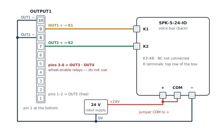
Red = +24 V · dark blue = 0 V · orange = K1 · green = K2 · dot = wires joined
From |
To |
Purpose |
|---|---|---|
+24 V — board OUTPUT24V pin 1 |
Box |
Box supply (through the board fuse F1) |
0 V — board OUTPUT24V pin 3 |
Box |
Box supply · OUTPUT1 pins 10 and 8 join this 0V |
Box |
Box |
Short jumper on the box |
OUTPUT1 pin |
Box |
Sound line 1 |
OUTPUT1 pin |
0 V |
OUT1 return |
OUTPUT1 pin |
Box |
Sound line 2 |
OUTPUT1 pin |
0 V |
OUT2 return |
OUTPUT1 has 10 pins with pin 1 at the bottom · leave OUTPUT24V pin 2 and the box K3–K8 and NC unconnected.
Note
Why COM is jumpered to + — the box manual shows two wiring styles. This board uses the “switch to 0V” style, which puts COM on the +24 V side. Every board output is an isolated optocoupler (PC817): the odd pin is the + side and the even pin is the − side. When an output turns on, current flows from COM through the K terminal to 0V, and the box sees that K terminal as ON.
Danger
🔴 Do not swap the odd and even pins — the odd pins (9 · 7) go to K, the even pins (10 · 8) go to 0V. Swapped, the box may play continuously and the board output may be damaged.
🔴 Do not use pins 3–6 (OUT3 and OUT4): they are the wheel motor enable relays.
Always switch the robot off before wiring.
Which output plays which sound
The box reads the K terminals as a binary number: K1 = 1 · K2 = 2, added together give the folder number.
OUT1 (K1) |
OUT2 (K2) |
Sound |
|---|---|---|
On |
Off |
|
Off |
On |
|
On |
On |
|
Off |
Off |
Stop |
Load audio into the three folders first, as described under “Loading audio files” in Wiring and audio files. One file per folder is simplest, because the box loops every file in the folder.
Test after wiring
You can test straight away, without starting the robot’s ROS system.
Power the robot. The box must stay silent (all outputs are off at boot).
Open the controller board settings page (
/board/) in Chrome or Edge, connect USB to the board’s Programming port, press Connect and wait about 10 seconds.Scroll to I/O · Opto output 1–10 and press สลับ (toggle) on OUT1. You should hear
AW001.Press สลับ on OUT1 again to switch it off. The sound must stop.
Try OUT2 alone for
AW002, and OUT1 with OUT2 forAW003.Set the volume with the knob on the back of the box (the I/O model has no volume control from the board).
Tip
No sound at all — check in this order
Is 24 V reaching the box (+ and − terminals)?
Is COM jumpered to +?
Are the odd output pins on K, not swapped with the even pins?
Are the box folders named
AW001, notAW1, with an MP3 or WAV file inside?
Important
If the sound keeps playing after the output is off, tell us. The board expects the box to play only while the output is held on. A box that latches the sound needs different board settings.
Let the board play the sounds
Board firmware 1.11.0 or later drives the I/O model by itself, following the robot’s events.
Event |
Sound |
Board setting |
|---|---|---|
Wheels moving |
|
|
Bumper hit |
|
|
E-stop pressed |
|
|
No event |
Stop |
— |
Set it on the board settings page, group 5 Voice box: spk_io = 2 (number of K lines wired) · spk_io_out = 1 (K1 is on OUT1).
Press Save to board, then Restart. After that, the OUT1 and OUT2 toggle buttons on the page no longer work, because the board uses those outputs for the voice box.
When several events happen together, the board plays the more important one: E-stop › bumper › reversing › wheels moving.